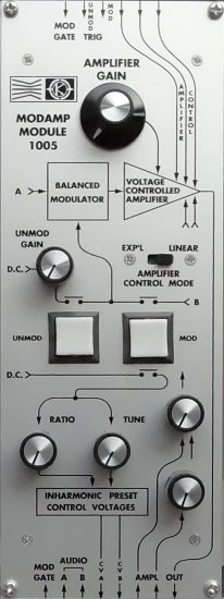
1005
Amplifier Gain
MOS-LAB 1005 is a circuit package containing a balanced modulator, a voltage controlled amplifier, and certain associated circuitry.
The balanced modulator can accept two input signals A and B in the frequency range from D.C. (Direct Current) to 20 kHz, and will produce the output function (A × B / 10).
If A and B are both sine waves of equal amplitude with respective frequencies f1 and f2, the output will consist of the sum and difference frequencies (f1 +f2) and (f1 −f2) only. The original frequencies f1 and f2 will be suppressed.
If A is a complex wave with harmonics f1, 2f1, 3f1, 4f1, 5f1, etc. and B is a sine wave of frequency f2, the resulting output will consist of the frequencies (f1 + f2), (f1 − f2), (2f1 + f2), (2f1 − f2), (3f1 + f2), (3f1 − f2), etc.
If f1 and f2 are chosen properly, the output will be a complex wave with inharmonic overtones. In electronic music this is extremely useful in simulating gong timbres, etc.
For the user’s convenience, Module 1005 contains circuits which produce two D.C. output control voltages, Va and Vb, which may be used to control two voltage-controlled oscillators which are supplying audio signals A and B respectively.
With a exponentially controlled oscillator such as the MOS-LAB 1004T module, the difference voltage Va − Vb controls the frequency ratio and the average voltage (Va + Vb) / 2 control the tuning of the input signals A and B. For the user’s convenience, ratio and tuning control knobs are located on the panel of the 1005 module.
The modulator can be activated or disengaged from the audio signal by pushing the illuminated push-button labelled ”Mod” and ”Unmod” on the front panel. With the ”Mod” button illuminated, audio signals A and B are modulated by one another as described in the specifications. With the ”Unmod” button illuminated, audio signal A is passed through the modulator unaffected and audio signal B is not used. A control is provided to adjust the gain when the ”Unmod” button is illuminated. The modulator may also be switched from ”Unmod” to ”Mod” by applying a Gate signal to the input marked ”Mod gate”.
When the gate signal is removed, the modulator will return to the ”Unmod” mode. On the other hand, the upper inputs labelled ”Unmod” and ”Mod” are latching and a pulse applied to either input will switch the operating mode to either ”Unmod” or ”Mod”. The mode will remain as set until a pulse is applied to switch to another mode or until the mode is changed by using the front panel push-buttons. The 1005 also contains a voltage controlled amplifier which may be controlled with external signals from either the upper or lower matrix switch section, or manually by means of a panel knob. A panel slide switch gives the user the choice of linear or exponential control modes.
TECHNICAL SPECIFICATIONS
BALANCED MODULATOR SECTION :
Output : Vout = (INA × INB)/10.
VOLTAGE CONTROLLED AMPLIFIER SECTION :
(Input attenuators fully clockwise) Vout: 0 to Unity, Linear Mode. Vout: -100 dB to 0 dB, Exponential Mode.


