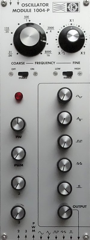
The MOS-LAB 1004-P Oscillator Module is a signal controlled waveform generator. Sine, triangle, square, sawtooth, and pulse outputs are available simultaneously. In addition, five dial knobs can be used to mix or algebraically sum these waveforms into an additional output. This module is particularly recommended for generating control waveforms and complex audio signals in the studio.
The output frequency range is from 0.03 Hz to 16,000 Hz in two ranges without external control signals, and the control signal range is 10 octaves on each range. Control signals may be either positive or negative, provided that the sum of the control signals does not drive the oscillator frequency beyond the above limits.
Controls
A coarse panel adjustment knob permits setting the zero-control-virtual-voltage frequency to anywhere within either of two ranges. The high range is the audio-frequency band, and the low range is a subsonic band. A fine adjust knob with a ±1 octave range is provided for accurate tuning.
Below the frequency adjustment knobs are a ON/OFF switch to turn the oscillator on and off, and a range switch to select the low subsonic or high audio-frequency band. A light below the ON/OFF switch will indicate, when the oscillator is on.. The PW panel-knob control permits manual adjustment of pulse width for the pulse waveform output.
The PWM panel-knob control adjust the modulation depth of the pulse-width modulation control input.
The two panel-knob controls (2 and 3) are used to modulate two frequency modulation inputs.
Outputs
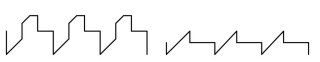
At the lower side, there are five waveform outputs, one for each waveform (sine, triangle, square, sawtooth, and pulse). In addition, the output in the lower right hand corner of the module is associated with the five dial knobs, one for each waveform, for a combination of waveforms to the one and same output. The sum of the five waveforms is associated with the attenuator marked ”OUTPUT” before being sent out of the module.
Inputs
The two frequency modulation inputs in the upper left hand corner of the module are fixed sensitive inputs: 1 virtual volt/octave. The two lower frequency modulation inputs (in positions 2 and 3) are associated with the two attenuators directly above the inputs (labeled 2 and 3). When the attenuators are rotated fully clock-wise, the input sensitivity is 1 virtual volt/octave. These controls are used to adjust frequency modulation depth. The last lower control input, designated PWM, is a pulse-width modulation control input, which is also provided with a panel-knob-actuated modulation depth control (the red knob)
TECHNICAL SPECIFICATIONS
OUTPUTS :
Frequency: 0.03 Hz - 16 kHz in two ranges without external inputs.
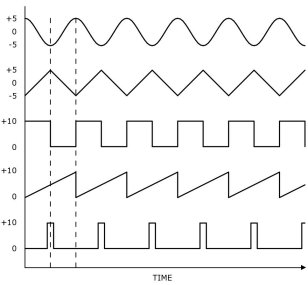
Sine: -5 volts to +5 volts.
Triangle: -5 volts to +5 volts.
Sawtooth: 0 volts to +10 volts.
Square: 0 volts to +10 volts.
Pulse: 0 volts to +10 volts.
INPUTS :
Frequency Modulation: 1 volt/octave.
Pulse Width Modulation: 10%/volt.
CONTROLS :
Frequency Range: Low (0.03 Hz - 32 Hz); High (31 Hz - 16 kHz).
Frequency, Fine: ±1 octave.
Frequency Modulation Depth (2)
Pulse Width: 0 - 100%
Pulse Width Modulation
TYPICAL WAVEFORMS PRODUCED BY MODULE 1004-P
1004-P
Oscillator