FUNCTION DESCRIPTION :
The 960 Sequential Controller has a wide variation of functions, both as an independent module and in combination with the 961 Interface and 962 Sequential Switch.
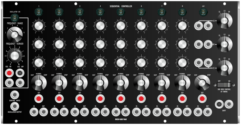
The sequence module consists of a voltage controlled clock oscillator which drives three rows of eight steps each. Indicator lights show sequence and step position statuts. A separate potentiometer for each step permits up to eight different voltage settings to be selected for each row. Voltage range switches for each row determine the DC voltage range of each pot. Jacks for trigger inputs and outputs appear below each column. Trigger inputs activate that stage independantly of the clock oscillator trigger. Trigger ouptuts are available for any others V-trigger activated input. Manual Trigger buttons as well, are included for each of the eight stages. Switches found immediately below each step position permit reset (this function, hidden, is not on the original 960, and active for all steps excepted step 1, 8 and 9) , normal, skip or stop functions. A ninth position providing skip (continuous progression through the eight steps) or stop (one progression to closure). Timing control for the eight steps is accomplished via the Third Row Control of Timing switch. This switch connects the third row of the sequencer into the control input of the clock speed for esch stage according to the settings on the third row potentiometers. The Shift input admits an external clock input to the sequencing circuit. This input may be usedin addition to or exclusive of the interna clock oscillator trigger. Manual shift from step to step is accomplished with the button next to the shift input jack., as well as individual manual trigger buttons for each step found under each step column.
The 960 version B offers a dual gate bus whose 2 Trigger outputs are on the left of the panel. Each step can be assigned to the trig 1 or 2 output via the switches which are on the same row as the "SET" buttons :
UP position: trig out 1
Center position : none
LOW position: trig out 2
ELECTRONIC SPECIFICATIONS :
Clock Oscillator :
Frequency Range : approximatively 0,1Hz to 500Hz, voltage controlled (1V/Oct)
Waveform Output : Rectangular wave, 90/10 % duty cycle (internally choosing by jumper)
Output Impedance : 1kΩ
Control Input Impedance : 100kΩ
Control Voltage Outputs :
Range Switches : X1 : 0 to 2 Volts
X2 : 0 to 4 Volts
X4 : 0 to 8 Volts
Power supply requirements : +12V@150mA / -12V@40mA