


1050
Mix-Sequencer
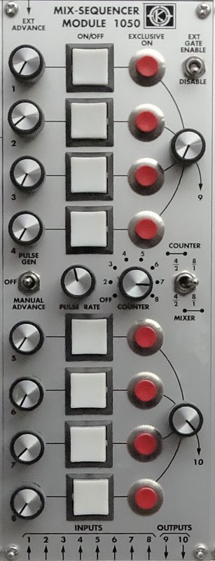
The MOS-LAB 1050 Sequential Mixer incorporates sequential switching functions necessary for rapid selection of preset waveforms and signals into a conventional audio mixer format. The Module 1050 contains two four-input mixers with gated inputs, an eight step counter and clock, and associated logic and switching circuitry. Each input has its own attenuator and each output has a master gain control.
The Module 1050 may be used as an eight input mixer with two adjustable outputs or as two separate four input mixers. A toggle switch at the right center of the panel couples the audio circuitry to provide either the 1 x 8 or two 1 x 4 mixer configurations.
A column of illuminated push-buttons indicates which inputs are gated on. The switches are pushed to change the state of an input, pushon/push-off. A column of ”Exclusive-on” pushbuttons will turn on a particular input while simultaneously turning all others off. This function is particularly useful for quick and convenient selection of preset signals. When the mixer is being used as two four-input mixers, the ”Exclusive-on” button affects all eight inputs.
The panel symbols around the ”Counter/Mixer” switch indicate how the switching logic (upper symbols) and audio circuitry (lower symbols) are set for the three switch positions. In the right position, the audio circuitry is coupled to form one eight-input mixer with two adjustable outputs. The logic is also set so that an ”Exclusive-on” button will affect all eight inputs. In the center position, the audio circuitry is again set up as an eight-input mixer.
With the ”Counter/Mixer” switch in the left position, both the audio circuitry and the logic circuitry are arranged as if the module were two separate four-input mixers. ”Exclusive-on” switches will affect either the upper or lower set of four inputs without interaction between sets. This position, and the center position of the ”Counter/Mixer” switch also permits ”Parallel step” operation of the sequencer, as shall be discussed below.
In addition to the manual switching operations described in the preceding paragraphs, the Module 1050 contains a clock pulse generator and an eight step counter. A toggle switch at the left center of the panel enables or disables the clock. When this switch is in the ”Pulse Gen” position, the counter will sequentially enable inputs to the mixer (and illuminate the appropriate indicator lamps) one at a time, resetting at the end of every cycle. The length of the cycle, i.e., the number of counts in a cycle, is determined by the rotary switch at the center of the panel. Setting this switch to the ”off” position disables the counter. The stepping rate is adjusted by the ”pulse rate” control. The counter may be manually advanced by either the front panel toggle switch or an External Advance pulse.
The ”parallel step” operation mentioned earlier permits the upper and lower sets of four inputs to be sequenced in tandem. In other words, the counter would actuate inputs in pairs: (1, 5), (2, 6), (3, 7), (4, 8).
The outputs of the counter or the front panel push-buttons can actuate a mixer input. Inputs can be held on by setting the appropriate pushbuttons even though the counter may be operating.
TECHNICAL SPECIFICATIONS
AUDIO INPUTS : ±10 volts.
AUDIO OUTPUTS : ±10 volts.